Phidget Spatial IMU with ROS
Bring up board 1044 over Noetic through the phidgets_drivers wrapper, then calibrate the compass so the heading means something
Overview
This article describes how to bring up a PhidgetSpatial 3/3/3 ↗ (Phidgets board 1044) and read it over ROS 1: first through the Phidget22 API, where quaternions come from the Spatial object’s AlgorithmData event, then through the phidgets_drivers ↗ ROS wrapper. Plus the compass calibration workflow, without which the heading output is garbage. My setup ran on a Jetson Nano with ROS Noetic, and the whole exercise has a destination: a four-wheel differential-drive mobile robot for experiments, whose odometry stack needs a trustworthy heading.
The board: PhidgetSpatial 3/3/3
The 1044 is a single USB board packing three 3-axis MEMS sensors: accelerometer (±8 g per axis), gyroscope and magnetometer. Hence “3/3/3”. Full specs are in the 1044 User Guide ↗; the short version for my purposes:
- One serial number, four channel types: the three individual sensor channels plus a combined Spatial channel.
- Magnetometer readings in gauss, plus a compass bearing derived from them.
- Data interval and change trigger are configurable per channel; mine sat at 256 ms for everything below.
My unit enumerates as “PhidgetSpatial Precision 3/3/3 High Resolution”, serial 301,849, firmware 403:
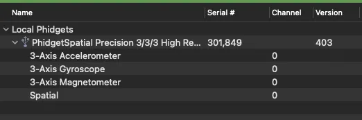 The 1044 enumerates four channel types: the three individual sensors plus the combined Spatial channel.
Quaternions from the Spatial object
In the Phidget22 API, the individual Accelerometer, Gyroscope and Magnetometer channel objects each fire their own data event. To work with quaternions, neither of those is what you want:
- Use the single Spatial object instead of the three individual channel objects.
- Normally you’d subscribe to the SpatialData event to have your program respond to the Phidget’s motion.
- To get updates as quaternions, subscribe to the AlgorithmData event instead; it carries the output of the onboard orientation algorithm (quaternion, plus heading).
The onboard algorithm is an AHRS by default because it fuses the magnetometer. Switch the Algorithm property to IMU to ignore the magnetometer in electromagnetically noisy environments. AlgorithmMagnetometerGain trades sensor noise against response time.
A single 1044 exposes all four channel types at once; what the ROS side does with them is next.
Bringing it up on ROS 1
The phidgets_spatial ↗ node from phidgets_drivers ↗ publishes:
/imu/data_raw(sensor_msgs/Imu): raw accelerometer and gyroscope data/imu/mag(sensor_msgs/MagneticField): raw magnetometer dataimu/is_calibrated(std_msgs/Bool): gyroscope calibration status; calibration runs automatically at startup and can be re-triggered any time via theimu/calibrateservice
Prerequisites
# IMU tools: imu_filter_madgwick and visualisation tools
sudo apt-get install ros-$ROS_DISTRO-imu-tools

# phidgets_drivers metapackage: libphidget22, phidgets_spatial, ...
sudo apt-get install ros-$ROS_DISTRO-phidgets-driversBoth are released as binaries for Noetic, so apt covers everything. Alternatively, build the noetic branch ↗ of ros-drivers/phidgets_drivers from source in a catkin workspace.
UDEV
Linux needs a udev rule so non-root users can open the USB device. The rules file ships inside the repo at phidgets_drivers/phidgets_api/debian/udev; it matches Phidgets USB devices (vendor 06c2) and sets MODE="666". The wiki documents the installer script; from your catkin workspace:
sh src/phidgets_drivers/phidgets_api/share/setup-udev.shand enter your sudo password when prompted.
Running
Start the spatial node; the defaults connect to any Spatial Phidget (serial: -1, hub_port: 0) and publish with frame_id: imu_link. Then run the Madgwick filter from imu-tools to fuse accelerometer, gyroscope and magnetometer into an orientation quaternion on /imu/data.
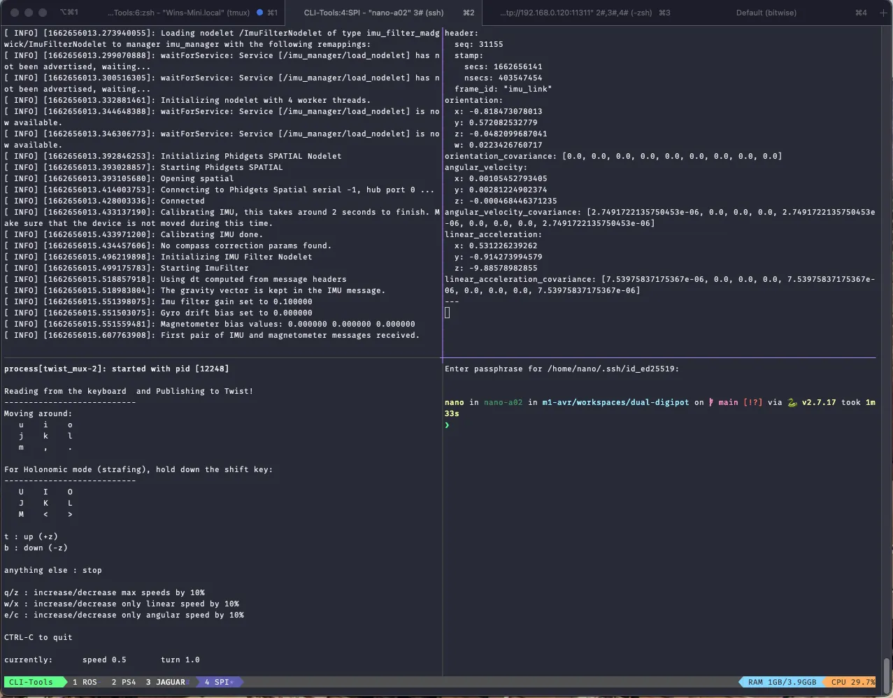
The screenshot below shows the full chain in tmux over SSH on the Nano: nodelet manager loading ImuFilterNodelet (imu_filter_madgwick), the Phidgets SPATIAL nodelet connecting, the automatic gyro calibration (it warns to keep the device still for around 2 seconds), and a rostopic echo of /imu/data with the quaternion in orientation.x/y/z/w.
The full chain in tmux on the Nano: gyro calibration, then the Madgwick-filtered quaternion on /imu/data.
Note the No compass correction params found line in the first screenful. That line ties the two halves of this article together:
- The onboard algorithm quaternions arrive through the Phidget API’s
AlgorithmDataevent, but the Noetic ROS driver publishes raw data by default and only enables onboard orientation estimation for newer hardware (use_orientation, MOT0109 and up). So with a 1044, quaternions in ROS come from the external Madgwick filter, not from the board’s own algorithm. - The heading part of that filter depends on the magnetometer, which needs compass calibration before its bearing means anything.
Compass calibration
The magnetometer reports the sum of all magnetic fields, and stationary interference from hard- and soft-iron distortion (up to ±3 gauss of it, per the user guide) skews the raw field vector. Phidgets’ Compass Calibration ↗ guide covers the procedure, and I have had extra reason to learn it properly: this board was bought in Vietnam and now lives in Canada. The correction parameters describe the magnetic environment around the board, and mine changed continents, so a fit from one country says nothing about the other; every move means recalibrating. My workflow:
-
Sanity-check the raw channels. Board flat and at rest: the accelerometer should read ≈ 1 g on Z and ≈ 0 g on X/Y, and the gyroscope ≈ 0 °/s on all axes.
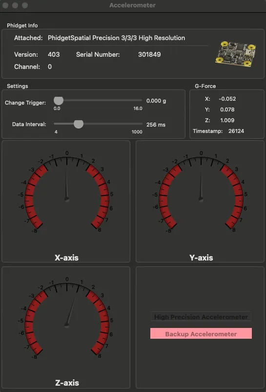 Board flat and at rest: ≈ 1 g on Z.
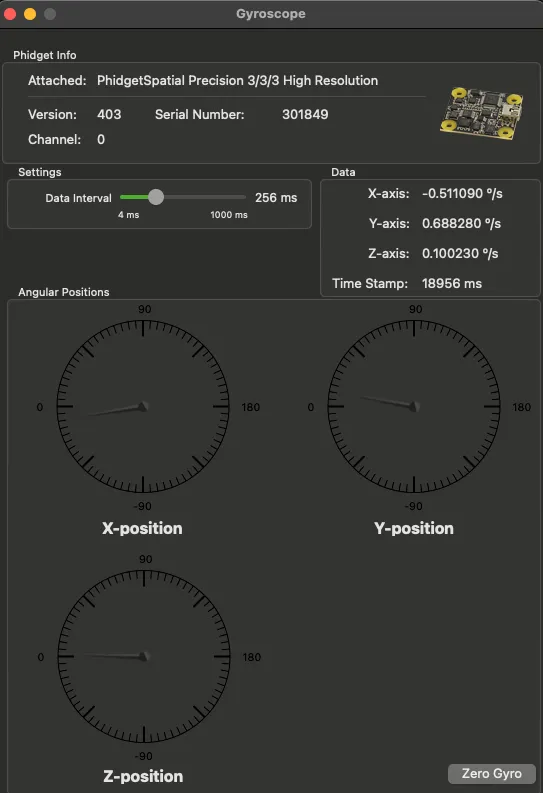 At rest the gyroscope reads near 0 °/s on all axes.
 -
Look at the raw magnetic field vector. The magnetometer view shows X/Y/Z in gauss plus the field direction, clearly distorted before correction.
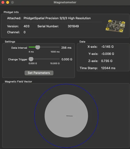 Raw magnetic field vector before calibration: clearly distorted.
 -
Run Phidgets’ Compass Calibrator. In the Magnetometer example, click Calibrate to open the Compass Calibration tool. Leave Local Field Strength at 1.0 (its magnitude doesn’t affect the heading), pick 3-axis since the board is free to rotate in all directions, hit Start, and slowly rotate the device away from magnetic interference until the red dots fill out as much of the sphere as possible. Stop, and the tool fits the correction parameters: the red cloud is the raw measurements, the green one the calibrated result. Repeat until the green sphere is centred.
The calibration values in the tool’s text box are what the Phidget22 API consumes via
setMagnetometerCorrectionParameters; on most Spatials they are also saved to flash, so the calibration survives power cycles. On the ROS side, the same numbers go into thecc_*parameters of thephidgets_spatialnode:cc_mag_field,cc_offset0–cc_offset2,cc_gain0–cc_gain2andcc_t0–cc_t5.
The end result is a stable calibrated compass bearing on the Spatial channel view: bearing 239.7°, pitch −2.9°, roll 4.4° on my desk:
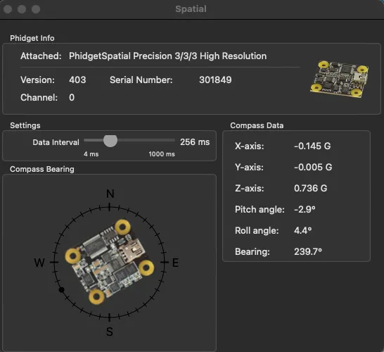 Calibrated compass bearing on the Spatial channel view: 239.7°, pitch −2.9°, roll 4.4°.
With /imu/data publishing a stable quaternion and the compass correction parameters in place, the IMU is ready to feed the odometry stack.
Acknowledgement
Driver and parameter details come from the phidgets_drivers ↗ wiki and the noetic branch README ↗; the calibration procedure follows Phidgets’ Compass Calibration ↗ guide and the 1044 User Guide ↗.