STM32F4 USB OTG and Modbus RTU
The Discovery board answers as a Modbus slave over a virtual COM port while a PyModBus harness asks the questions from the PC
Overview
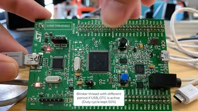
A take-home assignment for an interview asked me to talk to PLC-style machines and a HRI interface inside a high voltage control box. Those boxes run Modbus RTU, so I built a small demonstration of both sides of the conversation: an STM32F4 Discovery board acting as a Modbus RTU slave over its USB OTG port, and a Python harness on the PC doing the asking. The video below is the live demo.
One minute demo: board first, then the two Python scripts on the PC.
The nice part of this setup: no USB-to-serial adapter, no RS-485 dongle. The board’s own USB OTG port shows up on the PC as a virtual COM port, and Modbus RTU runs over it directly.
The firmware side
The board runs a small RTOS with a blinker thread, and that thread doubles as a status light: it blinks with a different period when USB_OTG is active, keeping the duty cycle at 50% either way. So before any protocol traffic happens, you can tell from across the desk whether the connection is up.
Two things come out of that USB port:
- A plain byte stream with board status, the words
process: onandprocess: offamong them. - Modbus RTU frames when a master asks. The slave mode supports a 16-bit CRC, and implements function code 1 (Read Coils) and function code 5 (Write Single Coil). Anything else gets a proper Modbus exception instead of silence.
The PC side with Python
Two short scripts drive the demo. The first one, usb_ser.py, opens the virtual COM port, reads the raw byte stream, decodes it, and appends it to a log file:
Decoded Byte: 1947fKM process: off
Decoded Byte: 1947fKM process: onThe second one, mb_tester.py, uses PyModBus ↗ as the Modbus master. Running it with pymodbus debug logging turned on is the best way to see what actually goes over the wire:
DEBUG:pymodbus:Running Current transaction state: IDLE
DEBUG:pymodbus:Changing transaction state from 'SENDING' to 'WAITING FOR REPLY'
DEBUG:pymodbus:Changing transaction state from 'WAITING FOR REPLY' to 'PROCESSING REPLY'
DEBUG:pymodbus:GET: Read Coils Response
DEBUG:pymodbus:Changing transaction state from 'PROCESSING REPLY' to 'TRANSACTION_COMPLETE'The demo walks through reads, then writes a single coil on and off, and finally pokes an address that is not implemented. The board answers with exception code 2, illegal data address, which is the correct way for a slave to say “ask me something I have”.
Why this simple demo is enough
On paper the demo looks almost too small: read some coils, write one coil, log a few bytes. But that is genuinely the whole vocabulary, and industrial machines do not speak a bigger one.
Every Modbus device, from a cheap power meter to a factory PLC, exposes itself the same way: coils for on/off facts (motor running, fault latched, door closed) and registers for numbers (temperature, vibration, current draw). Read Coils and Write Single Coil are the two verbs this slave implements, and they cover the two things a maintenance system ever does: read the machine’s state and occasionally tell it something. A real PLC just has more addresses and more data behind each one. The transport details this demo already handles, the 16-bit CRC, the request/response states, the exception replies, are identical in the field.
That matters for automated predictive maintenance, which is a boring loop when you get down to it: poll the machine on a schedule, log what comes back, and watch the trend lines. A bearing does not fail silently; current draw creeps up, vibration climbs, a coil that used to answer starts throwing exceptions. Catching that means having exactly what this demo has: a master that polls without being told, a device that answers with real state, and a script that decodes the stream and appends it to a log. The process: on/off bytes in the first script are the smallest possible version of that loop. Point the same PyModBus client at a real machine, run it from cron, and feed the log to anything that charts trends, and the loop scales from a desk demo to a control box.
The exception path is the part that matters for real use. A slave that goes quiet on a bad request stalls the whole polling loop; one that answers with exception code 2 lets the poller log it and move on. In a control box where the poller might be the only thing watching, that reply is what keeps the trend lines continuous.
References that made it work
The source note behind this post is basically a reading list, and these are the ones that earned their place:
- Modbus Tutorial from Control Solutions ↗: the plain-English Modbus 101, read this before touching a register.
- diagslave ↗: a free Modbus slave simulator. Testing the master script against a simulator before the hardware saved me a loop of “is it the code or the board”.
- PyModBus basic example on Stack Overflow ↗ and reading registers over RTU ↗: the two snippets that unblocked the client code.
- techbeast-org/modbus-tcp ↗: a minimal read-register script, useful as a sanity check.
- libmodbuspp ↗: the C++ wrapper around libmodbus, kept on the list in case the PC side ever needs to be native.
- Part 2 - Using Python to Read and Write data to Modbus ↗: the walkthrough I followed for the Python side.