Embedded Systems and Communication Protocols
Overview computer architecture and embedded system and serial communication implementation
Overview#
Embedded system is a system that has software embedded into the hardware and is dedicated to a particular part of a computer application regarding one or many specific features.
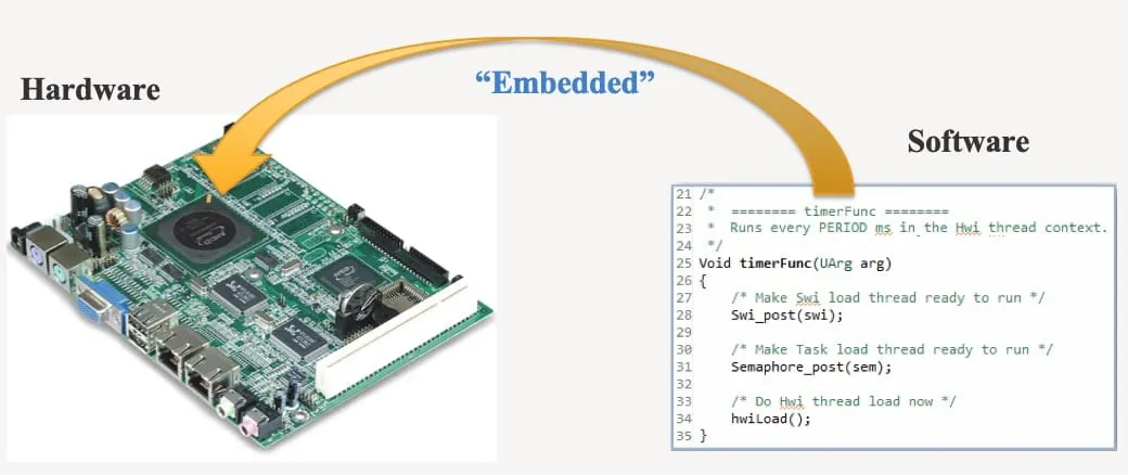 Understanding connection between Hardware and Software Interfaces. Source: RMIT VNM– EEET2490 (2017).
So, what is with the interests in embedded systems ↗?
99% of newly manufactured microprocessors were designed for Embedded Systems, whilst only 1% left for the rest of all desktop processors out in the market.
Over 31 billion MCUs was sold in 2015 and forecast to grow to almost 50 billion in 2019.
$10.46 billion in Embedded Software Market size valued in 2015 and is anticipated to grow at over 7% CAGR from 2016 to 2023.
System Architectures#
Before discussing different types of system, it is important to understand that a system essentially consists of data and instruction units which can loosely defined as human memory and brain respectively. From there, the idea is to access data, i.e. knowledge, to analyze and make instruction.
As previously mentioned, embedded systems are classified as MPU and MCU with primary differences which are important in design including application perspective, connectivity standpoints, power consumption and whether it is consumer electronic or industrial automation. More on that, detailed analysis ↗ by Product Managers from Microchip - a microcontroller manufacturer.
Beside that, their functionality are tabulated as below ↗.
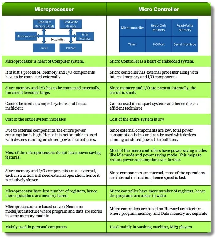 Microprocessor and Microcontroller specification and comparison. Source: ElectronicForum.
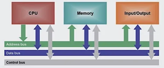
That being said, depends on the specific architecture, the medium for such transmission can serve different purposes (data/code) as well as interface with the CPU, memory and I/O units.
Hardware components and transmission interfaces. Source: RMIT VNM–EEET2490 (2017).
Harvard and Von Neumann#
The system architectures are commonly categorized essentially based on the design of their transmission interface. That is, a Harvard architecture with separate busses for data and instruction allowing simultaneous transfers on both busses. On the other hand, a Von Neumann with a single bus used for both data transfers and instruction fetches hence must be scheduled.
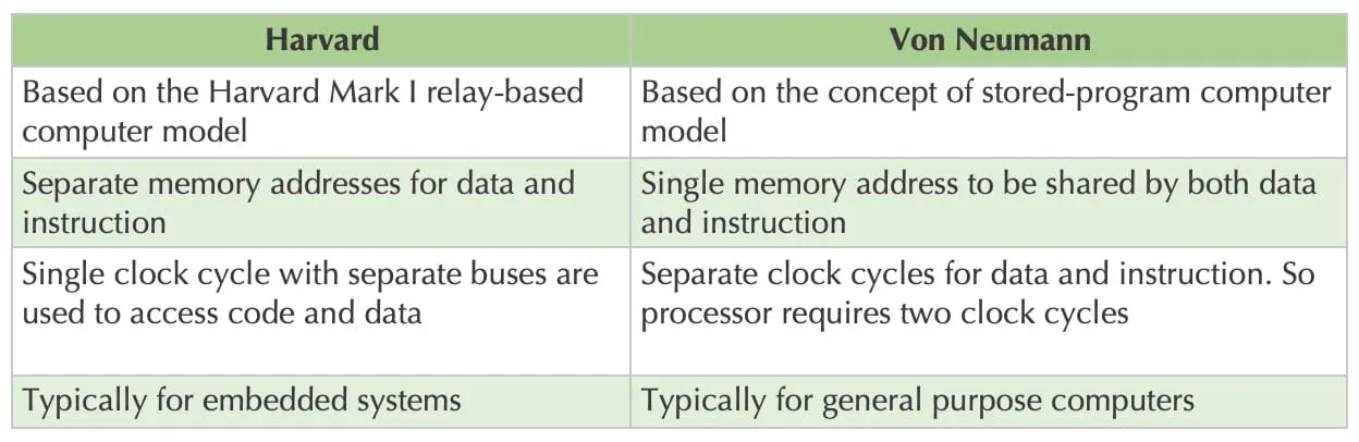 Design Concept, Memory Allocation, Computing Speed and Purpose comparison between architectures.
Communication Protocol#
The aforementioned medium typically a pre-defined sets of signal (voltage) leveling which referred as protocol and is a way for electronic components to exchange information hence the communication part.
There are two typical types of Electronic Communication Protocols, classified as:
-
Inter System Protocol: Between (External) Interconnected Different Devices. E.g: USB, RS232, UART/USART.
-
Intra System Protocol: Between (Internal) Intraconnected Entities, Submodules. E.g: SPI, I2C, CAN.
Some of the protocols are commonly implemented in industrial automation include USB, RS485, CAN. Although, three fundamental serial communication protocols will be examined for the purpose of an introduction.
UART#
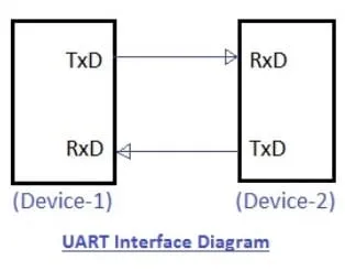 Universal Asynchronous Receiver Transmitter (UART) Hardware Setup and Interface.
It is a 2-wire, full-duplex, asynchronous and one-to-one serial protocol. Meaning it requires only 2 wires:
- Rx: Receiver
- Tx: Transmitter
to receive AND transmit at the same time (Duplex) while using their own CPU clocks, hence asynchronous and is typically used in scenario with two devices communicate to each other.
Commonly the 2-wire could be replaced with any general purpose input/output (GPIO) pin, a process supported by software library emulating the similar process at the hardware level, i.e. voltage. Hint: Software Serial ↗.
SPI#
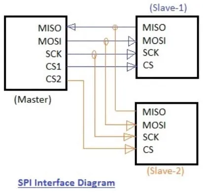 Serial Peripheral Interface (SPI) Hardware Setup and Interface.
It is a 4-wire, full-duplex, synchronous and one-to-(at least one) serial protocol and follow the master-slave interface scheme. Meaning it requires at least 4 wires:
- SS: Slave Select (aka. CS: Chip Select)
- SCLK: Serial Clock (aka. SCL)
- MOSI: Master Output, Slave Input
- MISO: Master Input, Slave Output
to receive AND transmit at the same time similar to UART with a designated CPU clock and a specific selected slave all of which initiated by the *one-and-only *master, hence synchronous and is usually implemented for scenario with only one master broadcast data, not necessarily identical, to different destinations.
The number of SPI-slaves is technically unlimited, however, realistically it is depend on the number of Slave Select (SS) pins, i.e. usually from 2 to 4 pins, and shift-register scheme for sequential interconnected slaves. More on that, SPI Direct and Daisy linked chains explanation ↗ from Maxim Integrated (Advanced).
I2C#
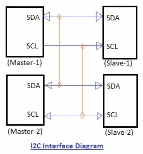 Inter-Integrated Circuit (I2C) Hardware Setup and Interface.
It is a 2-wire, half-duplex, synchronous and (at least one)-to-(at least one) serial protocol and also follow the master-slave interface scheme similar to SPI. Meaning it requires only 2 wires:
- SDA: Serial Data
- SCL: Serial Clock
to receive OR transmit sequentially, i.e. scheduled (half-duplex) different than UART or SPI. In spite of that, the beauty of I2C comes from both the world of UART and SPI with only two wire, multiple slaves, synchronous and especially multiple masters.
On a single bus (1 byte - 8 bits), I2C theoretically supports different addresses (slaves) which is a huge advantage over SPI with the Slave Select limitation dilemma. Realistically, the address of each slave is usually pre-defined under hardware level and conflict is inevitable, i.e. much less than 127 addresses.
Advantages / Trade-offs#
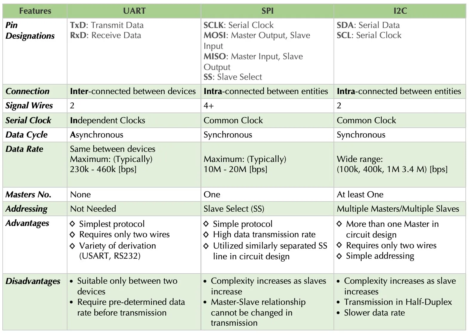 Summary and comparison between Serial protocols.