Portable Digital Multimeter using microcontroller
Measure DC voltage and current, resistance and capacitance with Arduino UNO board
Overview#
This project introduces a functional digital multimeter using basic components to measure DC voltage, DC current, resistance and capacitance. The objectives are low-cost, small and compact which driven by only a microcontroller ATmega328p and using the Arduino IDE for source code development. As a result, our DMM can function with all the features aforementioned including an auto-scale automation.
, Power Control Unit(PCU) and LCD Display")
Apparatus#
- Atmel Atmega328p
- 16Mhz Crystal
- USBasp Connector
- Shunt Resistor
- LM358 Operational Amplifier
- LCD 16x2
- LM7805 Voltage Regulator
- Fuse
- Buttons
- Piezo Buzzer
Measuring Voltage#
DC Voltage calculation is straight-forward since it depends entirely on the **Analog-Digital Converter (ADC)**module inside the Atmega328p. Although, it is important to lay out the conversion rate, especially the resolution since the power supply level, which is non-constant, play an active role in this formula.
Where the desired Voltage (Vcalc) is converted from an analog value (0-1023, or Resolution N = 1024) based on range of voltages. Also, the ADC resolution is specified for Atmega328p as 10 bits or 1024 voltage levels.
Or converted into code as
Vcalc = (analogRead(MEAS_VOLT_PIN) * Vrng6V) / MAX_ADC_VALUE;Measuring Current#
For DC Current, there are essentially two approaches, both of which has their advantages and trade-off. The first one is High-side Current Sensing attempting to measure current based on Ohm’s Law, i.e. via measured voltage, at very low level of resistance in order to capture the most accurate current.
Another alternative approach is using a Current Sensor which based on the Hall Effect.
High-side Current Sensing#
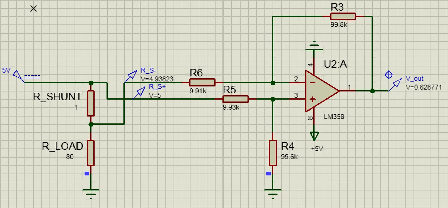
The High-side Current Sensing method employs a shunt resistor and a Difference Amplifier that differentiate and amplify the voltage across the shunt resistor. Specifically, the function and gain of amplifier stage can be understood as
where the Feedback resistor and Grounding resistor has the same ratio with respect to their input resistor and .
High-side Current Sensing Simulation using measured value with Shunt Resistor and LM358 Operational Amplifier
Specifically, the configuration with a gain set by the formula which results in the amplification of upto 10 times. As captured at the output of LM358, the output voltage actually captured at around .
With the use of 1Ω shunt resistor, the current is to be exact as the voltage with a mild variation for small resistive load and because of the resolution of Analog-Digital-Converter. The voltage input for microcontroller was read then converted back to the actual value of current ().
Imeas = analogRead(currentIn_pin) * getVcc() / MAX_ADC_VALUE;An alternative approach#
As mentioned, another approach is using the Hall Effect Current Sensor ACS712 which worked for both DC and AC current based on its output voltage which directly proportional to the magnetic field strength through it. Although, after several setup attempts, it was clear that due to the physic nature of this type of measurement and the potential high cost for an accurate current sensor and thus Hall Effect Current Sensor was deemed to be unfit for this kind of project.
Measuring Resistance#
The methodology to measure unknown resistance is essentially based on Voltage Divider circuit where the voltage source (VCC = 5V) is applied to two resistances in series, one of which is known and the other is the input unknown resistor.
Also, the voltage drop across one of two known resistances R10 or R1M is first read by the Analog Read in Arduino and instead of grounding the resistances, they are connected to 2 different digital input pins driven HIGH or LOW (grounding) in order to create AUTO RANGE between two scales (scale 1: 10 - 10 kΩ & scale 2: 10 kΩ - x MΩ)
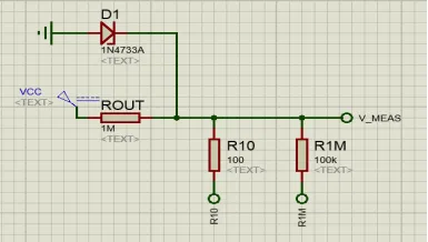 Resistance Measurement with the measuring resistance and Voltage Divider at the input pin
The conversion is then similar to that of the voltage measurement which using the ADC module but added a deterministic variable to enter the correct state based on the input value.
switch (res_state){
    case 1: getRange_R10(); if (rawADC > lThreshold) res_state = rngR10; else res_state = rngR1Meg; break;
    case 2: getRange_R1Meg(); if (rawADC < hThreshold) res_state = rngR1Meg; else res_state = rngR10; break;
}Connectivity#
In addition to resistance, the connectivity of a line can be detected by simply send in a small amount of current and detect other lead of the same line. Using a Digital pin D3 for input and another D4 for measurement, a closed loop of measurement can be formed where the D3 pin will send an output of HIGH-LOW (0-255) signal level and into D4. Next, the measurement pin will convert to digital signal (0-1) and act as the actuator if there is connectivity, i.e. digitalRead(D4) = 1
Measuring Capacitance#
There are two methods completely based on the functionality of a capacitor are used without any additional hardware usage as the advantages of the microcontroller ATmega328p.
Lower values#
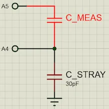
This can be done based on solely the functionality of ATmega328p and breadboard, i.e. the value of the stray capacitance and pull-up resistance. The microcontroller will output 5V at the Analog pin A5 (farahOut_pin) through the measuring capacitor and back to the Analog pin A4 (farahIn_pin).
cpct = (float) rawADC * IN_CAP_TO_GND / (float) (MAX_ADC_VALUE - rawADC);What was done is the raw ADC value is multipled with the stray capacitance IN_CAP_TO_GND and divided with the difference between raw analog value and the maximum resolution. The Stray capacitance varies from breadboard but usually has a consistent range from to .
 Capacitance Measurement with and without additional hardware
High values#
For high value of capacitance, however, it is required to have a better method in term of accuracy and thus charging seems more a viable solution. This method employ the use of microcontroller timer in order to capture the constant and later calculate the actual capacitance value.
do {
 digVal = digitalRead(farahOut_pin);
 // Compare charging time with real time
 unsigned long u2 = micros(); t = u2 > u1 ? u2 - u1 : u1 - u2;
} while ((digVal < 1) && (t < 400000L)); // Charging, do measurement

pinMode(farahOut_pin, INPUT); // Stop measurement
cpct = analogRead(farahOut_pin); // Read measured value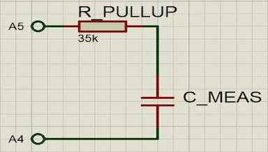 Capacitance Measurement with and without additional hardware